 The tolerances for compression springs are defined in accordance with DIN 2095 (DIN EN 15800). Quality grade 1 describes the smallest tolerance zone (higher product price) and quality grade 3 the largest tolerance zone. Our compression springs are manufactured to grade 2 (medium tolerance range) as standard.
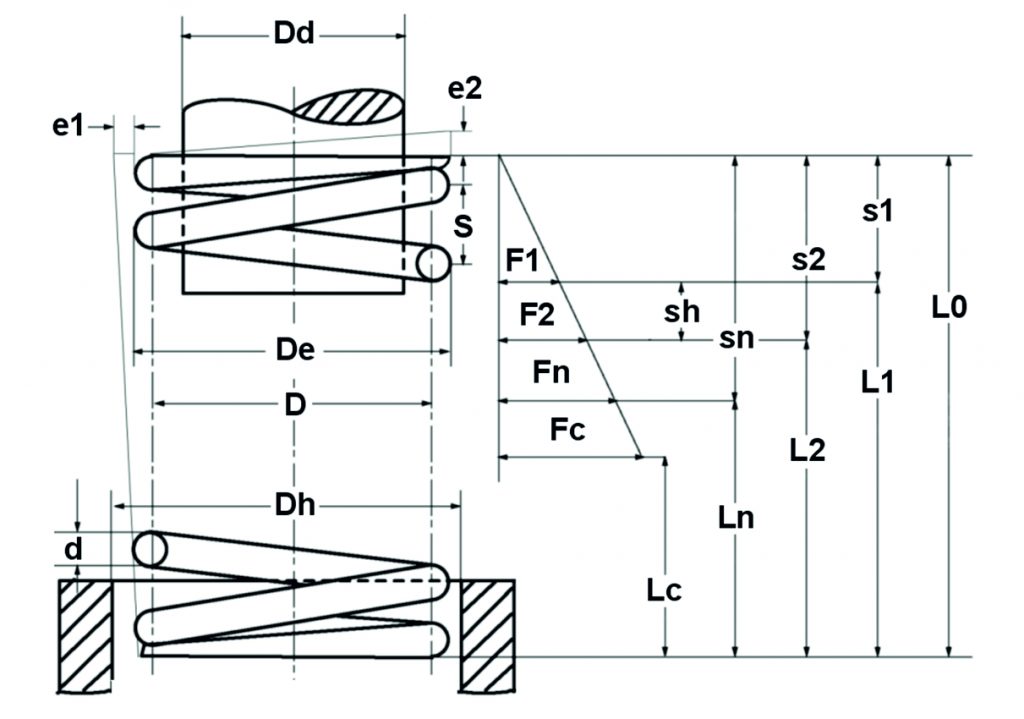
For compression springs, the coil diameter [Di, D, De], the deviation of the surface line [e1] and parallelism [e2], the untensioned length [L0] and the spring forces [F1, F2] are tolerated. DIN 2095 provides tolerance specifications in tabular form for the winding diameter and the deviation of the sheath line and parallelism. The tolerance values for the untensioned length [L0] and spring forces [F1, F2] are calculated on the basis of coulter diagrams. The tolerance calculation can be carried out using the Gutekunst spring calculation program.
Table of Contents
1st tolerance coil diameter [Di, D, De] Compression springs
The tolerance values for the coil diameter [Di, D and De] of a compression spring can be read from the following table of values for quality grades 1, 2 and 3 based on the average coil diameter [D] and the coil ratio [w].
Winding ratio: w=\frac{D}{d} (D=mean winding diameter, d=wire diameter)
| D (mm) | Maximum tolerance (+/- mm) Winding diameter [Di, D, De] |
||||||||
| Middle | Quality grade 1 |
Grade 2 (standard) | Grade 3 |
||||||
| Winding diameter | with winding ratio w | with winding ratio w | with winding ratio w | ||||||
| from – to | 4 – 8 | 8 – 14 | 14 – 20 | 4 – 8 | 8 – 14 | 14 – 20 | 4 – 8 | 8 – 14 | 14 – 20 |
| 0,63 – 1,00 | 0,05 | 0,07 | 0,10 | 0,07 | 0,10 | 0,15 | 0,10 | 0,15 | 0,20 |
| 1,00 – 1,60 | 0,05 | 0,07 | 0,10 | 0,08 | 0,10 | 0,15 | 0,15 | 0,20 | 0,30 |
| 1,60 – 2,50 | 0,07 | 0,10 | 0,15 | 0,10 | 0,15 | 0,20 | 0,20 | 0,30 | 0,40 |
| 2,50 – 4,00 | 0,10 | 0,10 | 0,15 | 0,15 | 0,20 | 0,25 | 0,30 | 0,40 | 0,50 |
| 4,00 – 6,30 | 0,10 | 0,15 | 0,20 | 0,20 | 0,25 | 0,30 | 0,40 | 0,50 | 0,60 |
| 6,30 – 10,00 | 0,15 | 0,15 | 0,20 | 0,25 | 0,30 | 0,35 | 0,50 | 0,60 | 0,70 |
| 10,00 – 16,00 | 0,15 | 0,20 | 0,25 | 0,30 | 0,35 | 0,40 | 0,60 | 0,70 | 0,80 |
| 16,00 – 25,00 | 0,20 | 0,25 | 0,30 | 0,35 | 0,45 | 0,50 | 0,70 | 0,90 | 1,00 |
| 25,00 – 31,50 | 0,25 | 0,30 | 0,35 | 0,40 | 0,50 | 0,60 | 0,80 | 1,00 | 1,20 |
| 31,50 – 40,00 | 0,25 | 0,30 | 0,35 | 0,50 | 0,60 | 0,70 | 1,00 | 1,20 | 1,50 |
| 40,00 – 50,00 | 0,30 | 0,40 | 0,50 | 0,60 | 0,80 | 0,90 | 1,20 | 1,50 | 1,80 |
| 50,00 – 63,00 | 0,40 | 0,50 | 0,60 | 0,80 | 1,00 | 1,10 | 1,50 | 2,00 | 2,30 |
| 63,00 – 80,00 | 0,50 | 0,70 | 0,80 | 1,00 | 1,20 | 1,40 | 1,80 | 2,40 | 2,80 |
| 80,00 – 100,00 | 0,60 | 0,80 | 0,90 | 1,20 | 1,50 | 1,70 | 2,30 | 3,00 | 3,50 |
| 100,00 – 125,00 | 0,70 | 1,00 | 1,10 | 1,40 | 1,90 | 2,20 | 2,80 | 3,70 | 4,40 |
| 125,00 – 160,00 | 0,90 | 1,20 | 1,40 | 1,80 | 2,30 | 2,70 | 3,50 | 4,60 | 5,40 |
| 160,00 – 200,00 | 1,20 | 1,50 | 1,70 | 2,10 | 2,90 | 3,30 | 4,20 | 5,70 | 6,60 |
2. tolerance of the surface line [e1] and parallelism [e2] compression springs
The tolerance values for the sheath line [e1] and parallelism [e2] of the compression spring in accordance with DIN 2095 (DIN EN 15800) can be found in the following table of values for quality grades 1, 2 and 3.
| Tolerance (+/- mm) Sheath line [e1] and parallelism [e2] | |||
| Quality grade 1 | Grade 2 | Grade 3 | |
| Tolerance e1 of the jacket line from the vertical |
0,03 L0 (1,7°) | 0,05 L0 (2,9°) | 0,08 L0 (4,6°) |
| Tolerance e2 of parallelism | 0.015 De (0.9°) | 0.03 De (1.7°) | 0.06 De (3.4°) |
3. tolerance of untensioned spring length [L0] and spring force [F1, F2] Compression springs
The tolerance of the compression spring for the untensioned spring length [L0] and spring force [F1, F2] can be calculated in the Gutekunst spring calculation program by specifying the dimensional data. To do this, go to the spring calculation program and enter the spring data (material, wire thickness [d], outer coil diameter [De], untensioned length [L0] and the number of spring coils [n]) for the calculation in the “by dimension” input fields. You can then read off the tolerance values (+/-) in the calculation result.
Related Links: