Before interpreting the Compression spring It should basically be clarified whether the intended type of stress is static, quasi-static or dynamic.
Table of Contents
Static or quasi-static stress
Time-constant (resting) load or time-changing load with less than 10,000 strokes in total or small stroke stresses of up to 0.1 x fatigue strength (τkh = τk2 -τk1).
Dynamic stress
Dynamic stress in springs is defined as stress that changes over time with more than 10,000 load changes or stroke stresses over 0.1 x fatigue strength (τkh) with constant and variable stroke stress. The spring is mostly pretensioned and exposed to periodic swell loads with a sinusoidal curve that occur randomly (stochastically), as is the case with vehicle suspension.
Depending on the required number of load cycles “N” without break, one differentiates:
1. The area of Fatigue strength with number of load cycles
N ≥ 10 7th for cold-formed springs
N ≥ 2 x 10 6th for thermoformed springs
With stroke voltage less than fatigue strength.
2. The area of Fatigue strength with number of load cycles
N< 10 7th for cold-formed springs
N< 2 x 10 6th for thermoformed springs
With stroke voltage greater than endurance stroke strength and less than time stroke strength.
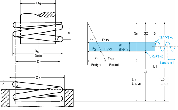
The existing shear stress is determined as follows.
Shear stress from force: \Large \tau=\frac{8DF}{\pi d^{3}}
Shear stress from path: \Large \tau=\frac{Gds}{\pi nD^{2}}
Description Formula symbol compression springs [PDF]
For dynamically loaded compression springs, the corrected shear stress applies due to the resulting increase in stress. With the tension correction factor k, which depends on the winding ratio (ratio of mean diameter to wire thickness) of the spring, the highest tension can be approximately determined.
Corrected shear stress :
τk1 = k · τ1< τko
τk2 = k · τ2< τko
where for k applies (according to Bergsträsser)
\Large k=\frac{\frac{D}{d}+0,5}{\frac{D}{d}-0,75}
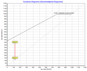
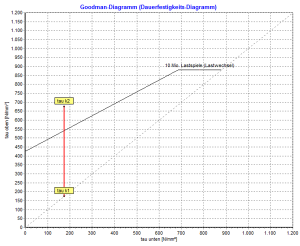
The permissible upper stress τko for each type of spring material is read from the fatigue strength diagram (Goodman diagram) from DIN EN 13906-1 (Fig. 12 to Fig. 22).
The desired working stroke must not exceed the fatigue strength (τkh):
τkh = τk2 – τk1< τkhzul
With the Gutekunst spring calculation program WinFSB every calculated compression spring can also be calculated for the dynamic application. All you have to do is activate the option “permanent” and “shot peened”. The dynamic values and the Goodman diagram are then displayed under the “Stress” area.
Important!
The block stress τczul should also be checked in order to take into account the stress superimposition due to natural vibrations of the spring body with dynamically loaded compression springs.
Dynamically stressed compression springs should be shot-peened before use. Shot peening compresses the surface layers so that a significantly better fatigue strength is achieved.
For the fatigue strength of a compression spring, the normal ones are particularly suitable for medium dynamic applications Spring steel wire EN 10270-1DH and SH, as well as the valve spring wires EN 10270-2-VDC, -VDSiCr, and -VDCrV for high dynamic applications.
Once corrosion or friction is through Mandrel or sleeve acts on the compression spring, the fatigue strength is no longer guaranteed!
For more information: