Every spring design of a compression spring consists of two stages :
1. The proof of function, with the verification of the dimensions, spring rate, forces, spring travel and vibration behavior.
2. The proof of strength, with the verification of compliance with the permissible stress or fatigue strength.
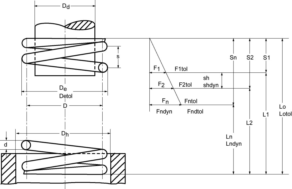
Table of Contents
Proof of function
The following applies to cylindrical compression springs made of wire with a circular cross-section.
Spring rate :
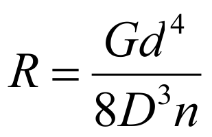
from R = F / s it follows …
Spring force :
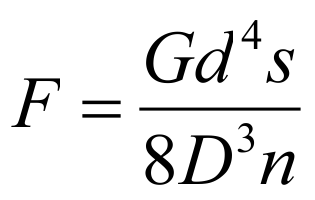
as …
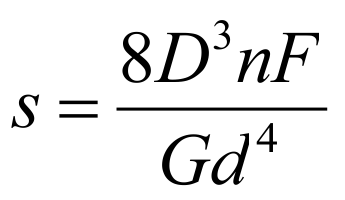
Suspension travel :
Proof of strength
After the spring dimensions have been determined, the strength must be verified. For this purpose, the existing shear stress is determined.
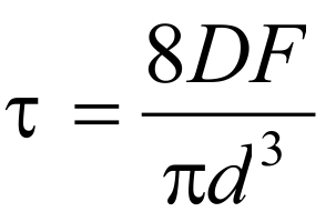
Tension from strength :
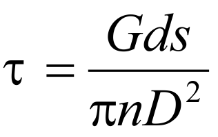
Tension out of way :
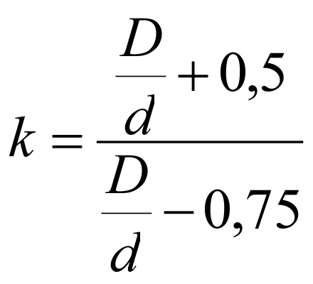
While the shear stress Ʈ is used for the design of statically or quasi-statically loaded springs, the corrected shear stress Ʈk applies to dynamically loaded springs. The shear stress distribution in the wire cross-section of a spring is uneven. The highest tension occurs on the inside diameter of the spring. With the tension correction factor “k”, which depends on the winding ratio (ratio of mean diameter “D” to wire size “d”) of the spring, the highest tension can be approximately determined. For dynamically stressed springs we get:
Corrected shear stress : Ʈk = k · Ʈ
where for k applies (according to Bergsträßer):
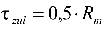
Now the comparison is made with the permissible voltage. This is defined as follows:
Allowable voltage:

The values for the minimum tensile strength Rm depend on the wire thickness and are in the relevant standards Materials to find. As a rule, it must be possible to compress compression springs up to the block length, which is why the permissible tension for the block length Ʈczul must be taken into account. At dynamic stress the lower and upper voltage (Ʈk1 and Ʈk2) of the corresponding stroke must be determined. The difference is the stroke voltage. Both the upper tension and the stroke tension must not exceed the corresponding permissible values. These are the fatigue strength diagrams of the EN 13906-1 to be found, or in Spring calculation program WinFSB to check ( Video compression spring calculation with WinFSB ). If the tensions stand up to this comparison, the spring is fatigue-resistant with a limit load cycle of 10 7th