Below is the summary of the basics about Spring design of Compression springs , Tension springs and Leg springs .
 Technical springs are still one of the most important machine elements today and are used successfully in vehicles, precision mechanical or electrotechnical devices, medical devices, household appliances and much more. The function of the entire device or machine part often depends on the trouble-free operation of the metal spring.
Metal springs are elements that deliberately deform under load and return to their original shape when the load is removed. The energy supplied is in Spring work (W) converted and released again at a later point in time (energy store). However, the metal springs only reliably perform this deformation and energy absorption within the limits designed for this purpose. Therefore is the right one Spring design and Spring calculation an important component for the perfectly working metal spring.
Table of Contents
The spring characteristic curve
Metal springs or technical springs are made according to your Spring characteristic judged. This spring characteristic represents the dependence of the Spring force (F) represents the spring travel (s). Because depending on which spring characteristic is required (linear, progressive, degressive or combined), the shape and type of the spring also change.
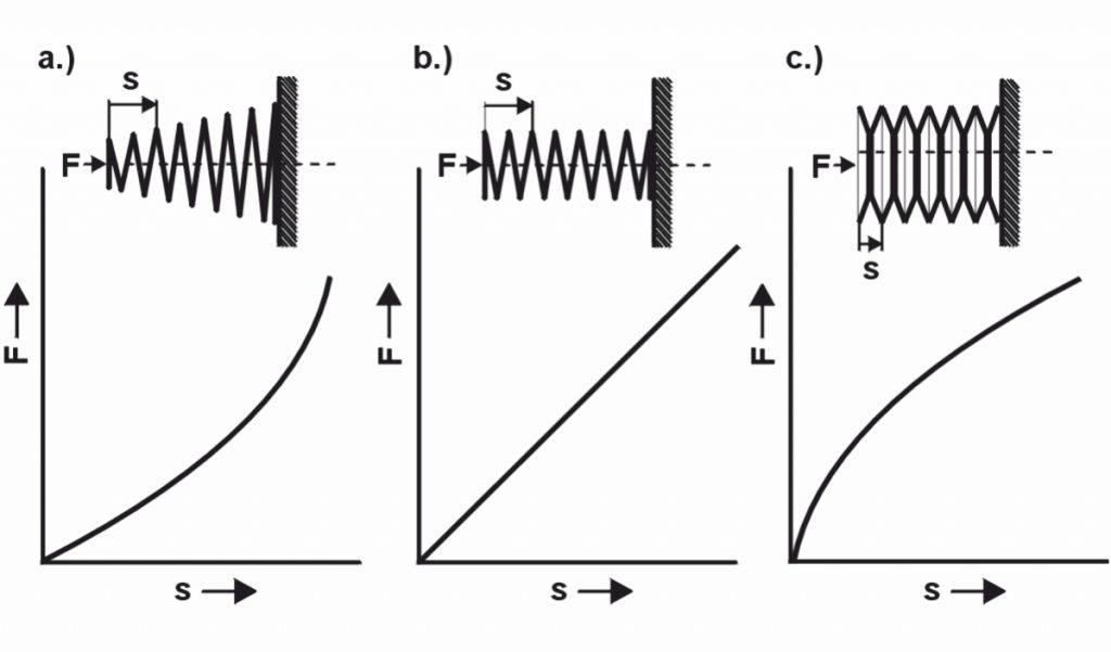
With the Spring rate (R) the spring characteristic is determined in the spring diagram. The spring rate (R) is therefore an important value when designing the spring for the right spring. At linear spring characteristic the spring rate is constant. Springs with a curved spring characteristic have a variable spring rate. The following formulas therefore apply to a linear characteristic:
for compression and tension springs
R=\frac{F2-F1}{s2-s1}for leg and torsion springs
R_{M}=\frac{M2-M1}{\alpha2-\alpha1}
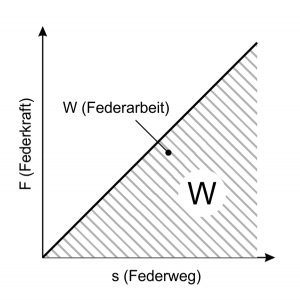
The spring work
When the metal spring is tensioned, work is done, which is then released again when the tension is released. The spring work (W) always results as the area below the spring characteristic. With a linear spring characteristic, the following applies:
for compression and tension springs
W=\frac{1}{2}F\cdot sfor leg and torsion springs
W=\frac{1}{2}M\cdot \alphaBy calculating the volume utility value, different types of springs can be determined using the ratio of spring work (W) and installation space (V) compare with each other:
\eta_{A}=\frac{W}{V}
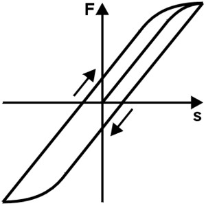
The hysteresis
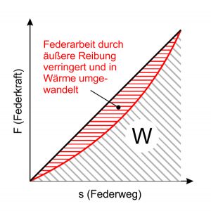
The suspension behavior can be influenced by external friction. These frictional forces hinder the spring’s recovery. In the case of alternating loads, this is expressed in the form of a Hysteresis loop . Part of the spring work is converted into heat by the friction and is then “lost”. Since this is undesirable when using springs, any friction should be designed by arrangement and Shape of feathers be avoided.
The relaxation
For example, if a compression spring is used higher temperature is compressed to a certain length between parallel plates, one can determine that the Spring force gradually decreases over time. This loss of strength increases with increasing temperature and tension.
Relaxation of the material is a plastic deformation that manifests itself as a loss of force with a constant installation length. This is given as a percentage of the output force F1:
Relaxation=\frac{\Delta F\cdot 100}{F1}The following diagram shows the basic course of the relaxation and the relaxation speed:
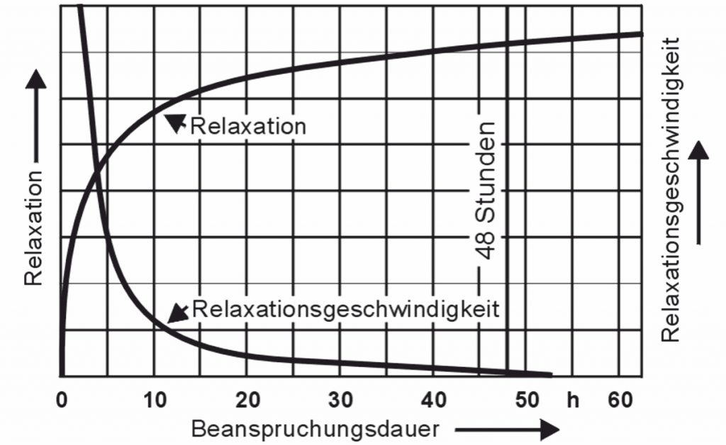
The relaxation values after 48 hours are considered to be characteristic values, although the relaxation is not yet completely complete at this point in time. Material-dependent relaxation diagrams can be found in EN 13906-1. These are only to be included by the designer if high demands are placed on the constancy of the spring force. The relaxation at different temperature states is used in the calculation in Spring calculation program WinFSB from Gutekunst Federn, available at www.federnshop.com , shown with.
The right choice of spring material
Metal springs must be manufactured from a suitable spring material and designed and shaped in such a way that they return to their original shape after the applied load has been removed. This property is expressed in the modulus of elasticity and in the sliding module. These Material parameters express the relationship between tension and elongation and should have as high a value as possible.
In addition, spring materials should:
- high elasticity limits, i.e. a large, purely elastic range,
- the corresponding tensions also at elevated temperatures endure without major loss of strength (low relaxation),
- have a high fatigue strength (fine-grain structure, free of impurities),
- have sufficient deformability,
- have a surface that is as slippery as possible,
- withstand certain requirements for corrosion protection,
- be electrically conductive or non-magnetic.
Elasticity and sliding moduli of various spring materials
| Spring material | Modulus of elasticity [N/mm²] | G module [N/mm²] |
| Patented drawn spring steel wire according to EN 10270-1 | 206000 | 81500 |
| Oil tempered valve spring wire according to EN 10270-2 | 206000 | 81500 |
| Hot rolled steel according to EN10089 | 206000 | 78500 |
| Cold rolled strip according to EN 10132 | 206000 | 78500 |
| X10 CrNi 18 8 (1.4310) | 185000 | 70000 |
| X7 CrNiAl 17 7 (1.4568) | 195000 | 73000 |
| X5 CrNiMo 17-12-2 (1.4401) | 180000 | 68000 |
| CuSn6 R950 according to EN 12166 | 115000 | 42000 |
| CuZn36 R700 according to EN 12166 | 110000 | 39000 |
| CuBe2 according to EN 12166 | 120000 | 47000 |
| CuNi18Zn20 according to EN 12166 | 135000 | 45000 |
| CuCo2Be according to EN 12166 | 130000 | 48000 |
| Inconel X750 | 213000 | 76000 |
| Nimonic 90 | 213000 | 83000 |
| Hastelloy C4 | 210000 | 76000 |
| Titanium alloy TiAl6V4 | 104000 | 39000 |
Influence of working temperature on spring material selection
Behavior at elevated working temperatures
The level of the working temperature can significantly influence the function of a spring, as the tendency to relaxation increases with increasing temperature. After evaluating the relaxation diagrams, the following limit temperatures can be set for the most important spring materials.
Limit temperatures of spring materials with minimal relaxation
| Spring material | Maximum working temperature in ° C at | |
| high load | low load | |
| Patented drawn spring steel wire according to EN 10270-1 | 60-80 | 80-150 |
| Oil tempered valve spring wire according to EN 10270-2 | 80-160 | 120-160 |
| X10CrNi 18.8 (1.4310) | 160 | 250 |
| X7CrNiAl 17.7 (1.4568) | 200 | 350 |
| X5CrNiMo 17-12-2 (1.4401) | 160 | 300 |
| CuSn6 | 80 | 100 |
| CuZn36 | 40 | 60 |
| CuBe2 | 80 | 120 |
| CuNi18Zn20 | 80 | 120 |
| Inconel X750 | 475 | 550 |
| Nimonic90 | 500 | 500 |
In addition, take the important for the spring function Material properties modulus of elasticity and shear modulus decreases with increasing temperature. Both the shear modulus and the modulus of elasticity are determined at higher temperatures using the following formula, with the material parameters at room temperature (20 ° C) serving as the basis.
G_{t}=G_{20}=\frac{3620-T}{3600}or.
E_{t}=E_{20}=\frac{3620-T}{3600}
This enables the designer to determine the actual spring forces at the expected operating temperature.
Behavior at low operating temperatures
When used in cooling systems, in space or when it is very cold in winter, temperatures as low as – 200 ° have to be endured. Despite rising tensile strenght low temperatures have an unfavorable effect, as the toughness of the materials decreases and brittle fractures can occur. Stainless spring steels as well as copper and nickel alloys are preferable to the patented spring wires and valve spring wires when used at low temperatures. The following table shows the limit temperatures.
Recommendations for use at low temperatures
| Spring material | Minimum working temperature in ° C |
| Patented drawn spring steel wire according to EN 10270-1 | -60 |
| Oil tempered valve spring wire according to EN 10270-2 | -60 |
| X10CrNi 18.8 (1.4310) | -200 |
| X7CrNiAl 17.7 (1.4568) | -200 |
| X5CrNiMo 17-12-2 (1.4401) | -200 |
| CuSn6 | -200 |
| CuZn36 | -200 |
| CuBe2 | -200 |
| CuNi18Zn20 | -200 |
| Inconel X750 | -100 |
| Nimonic90 | -100 |
Use of spring systems
For structural reasons, it is also possible to use several springs to absorb forces and movements. Simple Spring systems are Parallel – and Series connections .
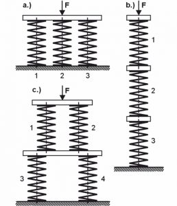
a) Parallel connection
The springs are arranged in such a way that the external load (F) is proportionally divided between the individual springs, but the travel of the individual springs is the same. So it results:
s=s1=s2=s3=... (total suspension travel)
F=F1+F2+F3+... (total spring force)
R=R1+R2+R3+... (total spring rate)
The spring rate of the overall system of a parallel connection is always greater than the spring rate of the individual springs
b) Series connection
The springs are arranged one behind the other, so that the same force acts on each spring, but the spring travel is divided between the individual springs. It results:
s=s1+s2+s3+... (total suspension travel)
F=F1=F2=F3=... (total spring force)
R=\frac{1}{\frac{1}{R1}+\frac{1}{R2}+\frac{1}{R3}+...} (Total spring rate)
The spring rate of the overall system of a series connection is always smaller than the spring rate of the individual springs
c) Mixed circuit
Several springs are connected in parallel and one behind the other. Because of the equilibrium, R1 = R2 and R3 = R4 must be. In the case shown, the following applies:
R=\frac{1}{\frac{1}{R1+R2}+\frac{1}{R3+R4}+...} (Total spring rate)
The spring rate of the overall system of the mixing circuit shown lies between the smallest and largest spring rate of the individual springs!
In the second part of the information series “ Design of metal springs – Part 2 “Calculation “we provide you with the calculation parameters for the Function and strength verification the Compression springs , Tension springs and Leg springs in front.
If you require an individual spring design, simply email us the key data for the metal spring you require to service@federnshop.com, contact our technical department by telephone on (+49) 035877 227-11 or use the Gutekunst spring calculation program WinFSB at www.federnshop.com for free calculation of compression springs, extension springs and torsion springs.
For more information: