In the first part of this two-part series Gutekunst Federn informed about the basics of spring design. In this second part you will find the concrete calculation data for the design of compression springs, extension springs and torsion springs (torsion springs). The Gutekunst spring calculation program WinFSB is also available for individual Gutekunst spring calculation program WinFSB.
The aim of the spring design of a compression spring, tension spring or torsion spring is to find the most economical spring for the given task, taking into account all circumstances, which also fits into the available space and achieves the required service life. In addition to these manufacturing and material requirements, the correct spring design is of particular importance.
Before calculating the spring, the following requirements of the metal spring should be compiled:
1. type of load (static or dynamic)
2. Lifetime
5. Required forces and spring deflections
6. available installation space
7. tolerances(compression springs, tension springs)
8. installation situation (buckling, transverse suspension)
Each spring calculation consists of two stages:
- Functional verification: Checking the spring rate, the forces and the spring travel, the vibration behaviour, etc.
- Strength verification
Check for compliance with the permissible stresses or proof of fatigue strength.
This requires an iterative approach.
The strength verification is based on the decision whether the spring is subjected to static, quasi-static or dynamic loading. The following criteria should be used for delimitation:
- Static or quasi-static loading: Static or quasi-static load constant over time (at rest) or load varying over time with less than 10000 strokes in total.
- Dynamic stress: time-varying loads with more than 10000 strokes. The spring is usually preloaded and subjected to periodic swell loading with a sinusoidal curve, which occurs randomly (stochastically), e.g. in motor vehicle suspensions. In some cases, abrupt changes in force occur.
When dimensioning the spring, stress limits must be specified which are based on the strength values of the materials and take into account the type of stress. For this purpose, a safety factor is included to determine the permissible voltage. After a comparison with the actual existing stress, the spring dimensioning must be revised by an iterative procedure. The following applies: Nominal voltage ≤ permissible voltage
Table of Contents
Calculation compression springs
General
Cold-formed cylindrical compression springs with constant pitch are most commonly used in practice. The wire is cold formed by winding around a mandrel. Depending on the feed of the rising pin, the coil spacing and the contact of the spring are regulated. After coiling, the spring is tempered in order to reduce residual stresses in the spring and to increase the shear elasticity limit. The set amount is therefore reduced. Tempering temperatures and times depend on the material; cooling takes place in air at normal room temperature.
Other important operations in spring production are grinding and setting. The spring ends are usually ground from a wire thickness of 0.5 mm to ensure plane-parallel bearing of the spring and optimum force transmission.
If the shear stress exceeds the permissible value when the spring is loaded, a permanent deformation occurs, which is expressed in the reduction of the unstressed length. This process is called “setting” in spring technology, which is associated with the terms “creeping” and “ relaxation “From materials engineering is to be equated. To counteract this, the compression springs are wound longer by the expected setting amount and later compressed to block length. This setting enables a better material utilization and allows a higher load in later use.
Calculation formulas cylindrical compression spring
The calculation of the compression spring is based on the calculation equations from DIN EN 13906-1:
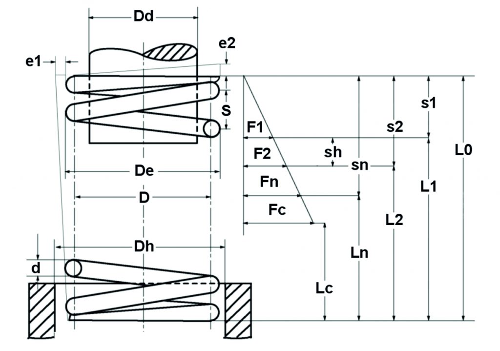
Figure: Theoretical compression spring diagram
Functional verification of compression springs
The following applies to cylindrical compression springs made of wire with a circular cross-section:
Formula spring rate: \Large R=\frac{ Gd^{4}}{8D^{3}n}
follows from R=F/s:
Spring force : \Large F=\frac{ Gd^{4}s}{8D^{3}n}
as well as:
Suspension travel : \Large s=\frac{8D^{3}nF}{Gd^{4}}
Strength verification compression spring
After the spring dimensions have been determined, the strength must be verified. For this purpose, the existing shear stress is determined:
Tension from force: \Large \tau=\frac{8DF}{\pi d^{3}}
Voltage from path: \Large \tau=\frac{Gds}{\pi n D^{2}}
While the shear stress \tau is to be used for the design of statically or quasi-statically loaded springs, the corrected shear stress \tauk applies to dynamically loaded springs. The distribution of shear stress in the wire cross-section of a spring is uneven, the highest stress occurs on the inside diameter of the spring. With the tension correction factor k, which depends on the winding ratio (ratio of mean diameter to wire thickness) of the spring, the highest tension can be approximately determined. For dynamically loaded compression springs, the result is thus:
Corrected shear stress: \Large \tau_{k}=k\tau
where holds for k (according to Bergsträsser):
\Large k=\frac{\frac{D}{d}+0.5}{\frac{D}{d}-0.75}Now the comparison is made with the permissible voltage. This is defined as follows:
Allowable voltage:
\Large \tau_{{zul}}=0.5\cdot R_{{m}}und
\Large \tau_{{czul}}=0.56\cdot R_{{m}}The values for the Minimum tensile strength Rm are dependent on the wire thickness and can be found in the standards of the corresponding materials.
As a rule, it must be possible to compress compression springs up to the block length, which is why the permissible stress for the block length is \tauczul to consider.
At dynamic stress must lower and upper voltage (\tauk1 and \tauk2) of the corresponding stroke can be determined. The difference is the stroke voltage. Both the upper tension and the stroke tension must not exceed the corresponding permissible values. These can be taken from the fatigue strength diagrams in EN 13906-1:2002. If the tensions stand up to this comparison, the spring is fatigue-resistant with a maximum number of load cycles of 107 .
Geometrical relationships for compression springs
| Spring parameter | Calculation equation |
| Total number of turns | nt = n + 2 |
| Block length of the ground spring | Lc = nt dmax |
| Block length of the unground spring | Lc = (nt + 1,5)dmax |
| Smallest usable length | Ln = Lc +Sa |
| Unstressed length | L0 = Ln +sn |
| Sum of the minimum distances between the windings | \Large S_{a}=\left (0.0015 \frac{D^{2}}{d} + 0.1d \right )\cdot n |
| Increase of the outer diameter under load
pitch |
\Large \triangle D_{e}=0.1\frac{S^{2}-08Sd-0.2d^{2}}{D}
\Large S=\frac{L0-d}{n} (ground) \Large S=\frac{L0-2.5d}{n} (unpolished)
|
|
Buckling spring deflection (valid for different bearing coefficients n, see EN 13906-1:2002) |
 |
All dynamically stressed springs with a wire thickness > 1 mm should be shot peened. This allows an increase in the continuous stroke strength to be achieved. After both the functional verification and the strength verification have been carried out, various geometry calculations must be carried out and taken into account in order to be able to fit the spring into the construction of the component. The block length cannot be fallen short of because the windings are tightly connected, the smallest usable length should not be fallen short of because then a linear force curve as well as dynamic load capacity are no longer guaranteed. In addition, the permissible tolerances according to DIN 2095 must be taken into account.
Tension spring calculation
General
Extensionsprings are wound around a mandrel in exactly the same way as compression springs, but with no coil spacing and with different eyelet shapes/spring ends to attach the spring. The windings are pressed tightly together in the production process. This internal preload F0 depends on the winding ratio and cannot be finished to an arbitrarily high level. The calculation software WinFSB from Gutekunst Federn provides reference values for the amount of preload after entering the respective spring data.
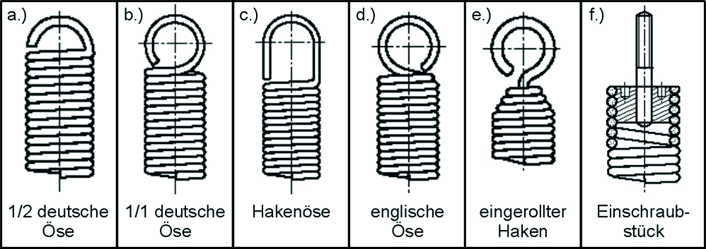
Image: Common eyelet shapes: a.) half German eyelet; b.) whole German eyelet; c.) Hook eye; d.) English eyelet; e.) rolled hook; f.) Screw-in piece
The advantage of extension springs is that they do not buckle; the disadvantage is the larger installation space and the complete interruption of the force flow in the event of spring breakage.
Calculation formulas cylindrical tension spring
Corresponding to the calculation equations for compression springs, but taking into account the prestressing force, the following relationships apply to cylindrical tension springs made of round wire (see also Figure 1.8):
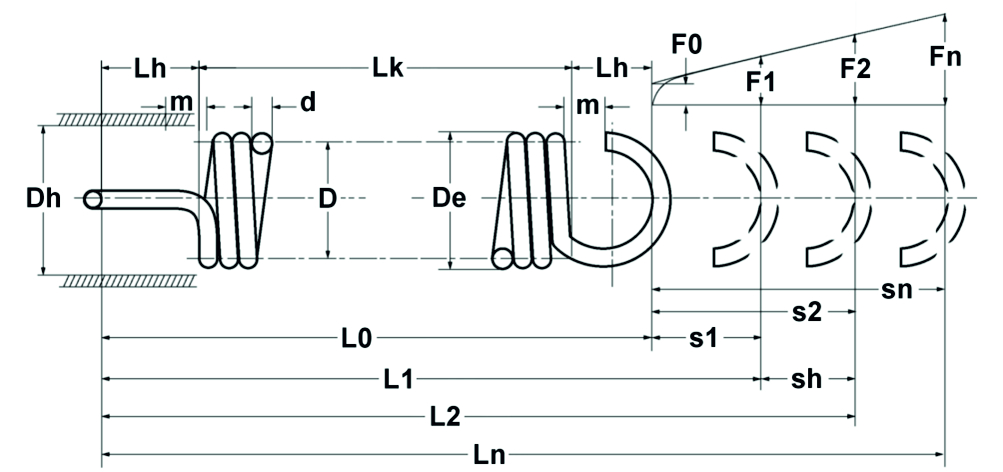
Figure: Theoretical tension spring diagram
Functional proof of tension spring
The following applies to cylindrical tension springs made of wire with a circular cross-section:
Spring rate: \Large R=\frac{Gd^4}{8D^3n}=\frac{F-F0}{s}
follows from R=F/s:
Spring force: \Large F=\frac{Gd^4s}{8D^3n}+F0
as well as:
Spring travel: \Large s=\frac{8D^3n(F-F0)}{Gd^4}
Strength verification of tension springs
As with compression spring calculations, the existing shear stress must be determined.
Shear stress: \Large \tau=\frac{8DF}{\pi d^3}
Likewise, the corrected stroke stress must be calculated for dynamic loading.
Corrected shear stress: \Large \tau_{{k}}=k\tau
Permissible voltage: \Large \tau_{{zul}}=0.45 \cdot R_{{m}}
The existing maximum voltage \taun for the largest travel sn is set equal to the permissible voltage. However, in order to avoid relaxation, only 80% of this spring travel should be used in practice.
\Large s_{{2}}=0.8 \cdot s_{{n}}No generally valid fatigue strength values can be given for dynamic stresses, as additional stresses may occur at the bending points of the eyelets, some of which may exceed the permissible stresses. Tension springs should therefore only be subjected to static loads if possible. If dynamic stress cannot be avoided, one should go for angled Eyelets do without and use rolled or screwed-in end pieces. A life test under later operating conditions makes sense. A Surface hardening by shot peening is not feasible because of the tight turns.
Geometrical relationships for tension springs
| Spring parameter | Calculation equation |
| Body length | LK = (nt+ 1)d |
| Unstressed length | L0 = LK + 2 LH |
| Eyelet height half German eyelet | LH = 0.55Di to 0.80Di |
| Eyelet height whole German eyelet | LH = 0.80Di to 1.10Di |
| Eye height hook eye | LH > 1.10Di |
| Eyelet height English eyelet | LH = 1.10Di |
The permissible manufacturing tolerances according to DIN 2097 must be taken into account.
Calculation of torsion springs (torsion springs)
General
Coiled cylindrical torsion springs have essentially the same shape as cylindrical compression springs and extension springs, but with the exception of the spring ends. These are bent in a leg shape to allow the spring body to rotate around the spring axis. This means that they can be used in a wide range of applications, e.g. as return springs or hinge springs. The torsion spring should be mounted on a guide mandrel and the load should only be applied in the winding direction. The inner diameter is reduced in this case. The springs are usually coiled without pitch. However, if friction is absolutely undesirable, torsion springs can also be manufactured with coil spacing. In the case of dynamic loading, care must be taken to ensure that there are no sharp-edged bends at the ends of the springs in order to avoid unpredictable stress peaks.
Calculation formulas cylindrical torsion springs (torsion springs)
The calculation is carried out according to the guidelines of EN 13906-3:2001:
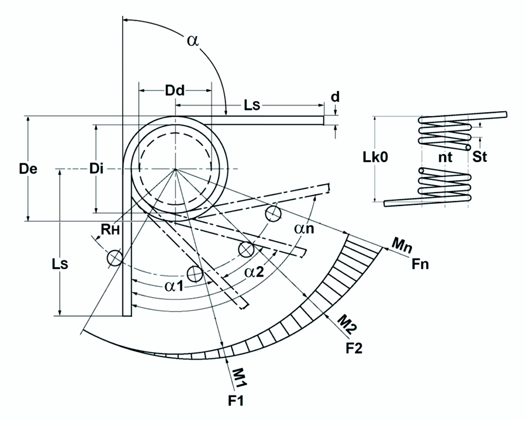
Figure: Theoretical torsion spring / torsion spring diagram
Functional verification of torsion springs (torsion springs)
Fed Mom Rate: \Large R_{M}=\frac{M}{\alpha}=\frac{d^4E}{3667Dn}
Spring moment: \Large M=FR_{H}=\frac{d^4E\alpha}{3667Dn}
Angle of rotation: \Large \alpha=\frac{3667DMn}{Ed^4}
Strength verification of torsion springs (torsion springs)
The existing bending stress is determined and compared with the permissible stress. In the case of dynamic loading, the corrected stress must again be used for comparison.
Bending stress: \Large \sigma=\frac{32M}{\pi d^3}
Corrected bending stress: \Large \sigma_{{q}}=q \sigma
where q is:
\Large q=\frac{\frac{D}{d}+0.07}{\frac{D}{d}-0.75}
Permissible bending stress: \Large \sigma_{{zul}}=0.7Rm
At dynamic stress must lower and upper voltage (tk1 and tk2) of the corresponding stroke can be determined. The difference is the stroke voltage. Both the upper tension and the stroke tension must not exceed the corresponding permissible values. For spring steel wire, these can be taken from the fatigue strength diagrams in EN 13906-3:2001. If the tensions stand up to this comparison, the spring is fatigue-resistant with a maximum number of load cycles of 10 7 .
Geometric relationships for torsion springs (torsion springs)
| Spring parameter | Calculation equation |
| Reduction of the inner diameter at maximum load | \Large Di_{n}=\frac{Dn}{n+\frac{\alpha}{360}}-d |
| Unloaded body length | \Large Lk=(n+1.5)d |
| Body length in maximum loaded condition | \Large Lk_{n}=(n+1.5+\frac{\alpha}{360})d |
| Spring travel | \Large s_{n}= \frac{\alpha_{n}R_{H}}{57.3} |
In addition, the manufacturing tolerances according to DIN 2194 must be taken into account.
A summary of the article “Design of a metal spring”, consisting of part 1 “Basics” and part 2 “Calculation”, is also available for download in the Gutekunst Federn 1×1.
If you require an individual spring design, simply email us the key data of the required metal spring to service@gutekunst-co.com, contact our technical department by telephone on (+49) 035877 227-11 or use the Gutekunst spring calculation program WinFSB at https://www.federnshop.com for free calculation of compression springs, extension springs and torsion springs.
For more information: